3. Data o provozu metra v Praze a jeho řídicích systémů
Data o provozu metra – Pražské metro je velký komplexní, tzn. velmi složitý, systém. Každý složitější systém se skládá z několika subsystémů, vazeb a toků mezi nimi. Subsystémy lze dělit z hlediska řízení na řízené a řídicí. Další oblastí jsou systémy zabezpečovací, které plní bezpečnostní funkce, tj. zmírňují rizika, anebo plní důležitou funkci, jejíž výpadek nebo špatné provedení vede k zvýšení rizika nebo přímo k nehodě [4]. Systém pražského metra lze obecně rozdělit na samostatné provozní subsystémy (stanice, vlaky, infrastruktura), řídicí systémy (vozové počítače, dispečerská ovládací centra, sdělovací technika) a systémy zabezpečovací, které zmírňují dopady při realizace rizik (zabezpečovací zařízení, návěstidla, automatická stavědla).
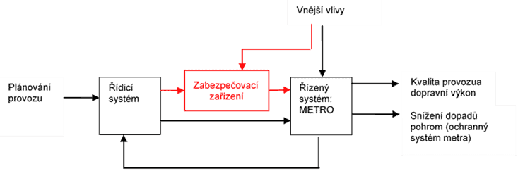
Obrázek 10 popisuje vztahy mezi řídicími, zabezpečovacími a řízenými systémy. Vnější vlivy přímo ovlivňují systémy a mohou způsobit vnitřní chyby systému, které mohou vést k nebezpečným událostem. Z těchto důvodů se mezi řídicí a řízené systémy instalují systémy zabezpečovací, plnící bezpečnostně relevantní funkce, které využívají vstupů řídicích systémů nebo identifikují nepřijatelné poruchy systému či nepřijatelné vnější vlivy a vykonají svojí funkci tak, aby řízený systém uvedli do bezpečného stavu, tj. stavu v které neohrozí sebe ani své okolí.
Systém řízení metra, tak jako i jiné systémy řízení městské kolejové dopravy, jsou systémem distribuovaným. Distribuované systémy jsou složeny ze subsystémů (uzlů), které vykonávají dané funkce samostatně bez vazby na druhé, ale jejich propojením lze plnit jiné funkce na vyšších úrovních. Subsystémy distribuovaných systémů tedy vykonávají některé funkce samostatně a jiné funkce až po propojení více subsystémů (uzlů), čímž dostaneme komplexní distribuovaný systém se vzájemnými závislostmi [4].
Bez ohledu na vykonávanou funkci, lze subsystémy metra dále rozdělit do kategorií:
- stacionární systémy – traťové, staniční a dispečerské,
- mobilní systémy – vlaky a jejich zařízení.
Dále uvedený popis pražského metra vychází z práce [4].
3.1 Pražské metro jako řízený systém
Systém řízení pražského metra plní dvě základní funkce – dopravní a ochrannou. Ochranná funkce snižuje dopady pohrom. Dopravní funkce je řízena ze střediska plánování městské dopravy, ze kterého vychází požadavky v podobě jízdních řádů a požadavků na kvalitu provozu. Uvedené požadavky jsou plněny řízenými systémy, tj. infrastrukturou (dopravními cestami a stanicemi), dopravními prostředky a návaznými pomocnými systémy.
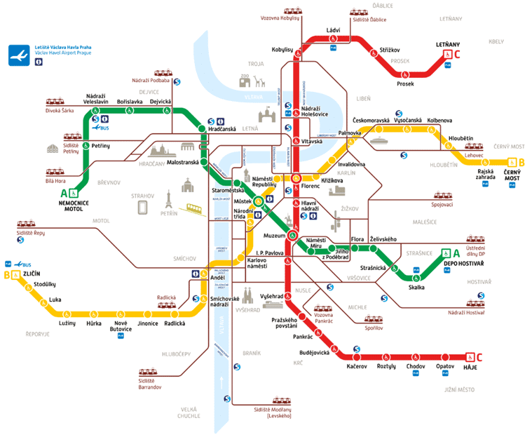
Síť metra tvoří páteř celého systému MHD v Praze. Cestující mohou využívat 61 stanic na třech linkách A, B, a C, jejichž délka činí cca 65 km [4,11]. Doprava je vedena na trati umístěné v tunelu, odděleného od okolního prostředí. Pouze v některých úsecích v oblasti depa je provoz vlaku ve venkovním prostoru. Trať je fyzicky oddělená od okolní infrastruktury a neumožňuje přímé napojení jiných dopravních prostředků městské a příměstské dopravy (vlaky příměstské dráhy).
Vozový park čítá dle zdroje [11] cca 730 vozidel, rozmístěných ve 3 depech: Kačerov, Zličín a Hostivař. V pražském metru se používají dva základní typy vozů spojovaných do pětivozových souprav. Vozy typu M1 zajišťují provoz na lince C a jsou vypravovány z depa Kačerov. Druhý používaný typ, zajišťující provoz linek A B, nese označení 81-71M a jedná se o vozy vzniklé rekonstrukcí starších sovětských vozů typu 81-71 [4,11]. Rozložení tras metra je znázorněno v mapě na obrázku 11.
Technologie řízeného systému tvoří samostatné jednotky, které zajišťují hlavní nebo podpůrné funkce provozu. Předmětné jednotky jsou ovládané (řízené) z místa na ovládacím pultu jednotky (tzv. místní ovládání) nebo ze vzdáleného, centralizovaného ovládacího střediska. Zmíněná střediska jsou buď umístěna v technologických místnostech stanic, nebo na centrálním dispečinku metra. Z výše uvedeného je patrné, že do technologické části patří řídící a zabezpečovací systémy metra, ale pro účely předložené práce jsou řídicí a zabezpečovací systémy rozděleny do zvláštních kategorií [4]. Technologické systémy metra dle [4,72] zahrnují:
- energetická zařízení:
- měnírny a distribuční transformovny (trasy stanice metra jsou napájeny několika napájecími zdroji 22 kV, každá stanice má navíc svůj záložní zdroj UPS pro případ výpadku elektrické energie, zabezpečovací a řídicí systémy mají také vlastní nezávislé zdroje),
- zabezpečovací zařízení (staniční, traťové a jejich napájení),
- sdělovací zařízení:
- sdělovací kabely,
- VKV spojení s vlaky,
- zařízení pro automatické odbavování cestujících,
- zařízení průmyslové televize, telefonní zřízení, rozhlasové zařízení,
- hodinové zařízení, elektrickou požární signalizaci,
- elektrickou zabezpečovací signalizaci,
- strojní zařízení:
- pohyblivé schody ve stanicích,
- čerpací stanice ve stanicích a mezistaničních úsecích,
- výtahy ve stanicích,
- dílny a sklady údržby ve stanicích,
- vzduchotechnická zařízení:
- hlavní větrání,
- staniční vzduchotechnika,
- ASDŘ – automatizovaný systém dálkového řízení,
- mobilní stroje a zařízení:
- vozový park,
- zařízení a prostředky pro čištění odpadu, která zahrnují mycí a zametací vozíky, kontejnery na odpad a soustavu žebříků a lešení pro čištění osvětlovací techniky,
- · prostředky požární ochrany umístěné ve stanicích, které umožňují rychlý zásah při požáru v podzemních prostorách.
3.2 Zabezpečovací zařízení
Zabezpečovací zařízení v drážním provozu, konkrétně v provozu metra zajišťují bezpečný provoz vlaků na trati. Jejich hlavním úkolem je snížit realizace rizik spojených s nepřiměřenou rychlostí vlaku, špatným nastavením jízdní cesty (obrana proti střetu vlaků) a podobně. Zabezpečovací zařízení se dělí do tří základních skupin [4]:
- staniční zabezpečovací zařízení (SZZ),
- traťová zabezpečovací zařízení,
- vlaková zabezpečovací zařízení (VZZ).
Účelem staničních zabezpečovacích zařízení je zabezpečení vlakových jízdních cest tak, aby se zabránilo střetu vlaků, tj. aby se zajistil bezpečný průjezd navolenou jízdní cestou. V pražském metru se provozuje reléové zabezpečovací zařízení AŽD 71 přizpůsobené pro provoz metra. V nových stanicích a ve vybraných stanicích metra s kolejovým větvením se provozuje elektronické zařízení (SZZ) typu ESA 11 M s napojením na reléová zařízení.
Ve vybrané typové stanici je instalováno zařízení ESA 11 M, které se ovládá buď místně z ovládacího PC zařízení, nouzově z nouzového panelu, vzdáleně na zařízení ASDŘ-D ve stanici pracovníkem SPT (samostatný provozní technik) nebo pomocí systému ASDŘ-D na pracovišti vlakového dispečera z centrálního dispečinku. Staniční nebo traťové zabezpečovací zařízení se také označuje angl. Interlocking [4].
Traťové zabezpečovací zařízení zabezpečuje jízdu následných vlaků a vylučuje jízdu protisměrných vlaků na jedné koleji. V případě pražského metra provozované reléové zařízení AŽD 71 a ESA 11 M [4].
Vlaková zabezpečovací zařízení zabezpečuje příjem návěstních znaků hlavních návěstidel a návěstidel autobloku na vlak a samočinné zabrzdění vlaku, jestliže strojvedoucí nereaguje na návěst nařizující snížení rychlosti nebo zastavení. V mezinárodním pojetí jsou VZZ součástí systému ATC (Automatic Train Control), která se dělí na části ATP (Automatic Train Protection) a ATO (Automatic Train Operation) [4,71,73].
Systém ATP je umístněný ve stanici a na trati, který zasílá řídicí zprávy do mobilní části ATP na vlaku. Vlak příslušná data přijímá a pomocí jednotky ATP zpracovává informace, vyhodnocuje je a provádí příslušné operace. Mobilní jednotka ATP spolupracuje s jednotkou ATO, která ovládá jízdu vlaku, zajišťuje tzv. automatické vedení vlaku podle režimu, na který je režim jízdy vlaku nastaven. V plně automatickém režimu, jednotka ATO ovládá rozjezdy a plynulou jízdu.
Často jednotka ATO vykonává i běžné funkcemi vlaku, jako je automatické hlášení, otevírání a zavírání dveří a podobně. V případě manuálního provozu metra, systém provádí pouze bezpečnostní funkce, kterými jsou například hlídání maximální povolené rychlosti (udaní jízdním profilem, snížené strojvedoucím nebo vzdáleně jiným pracovníkem skrze systém ATP a podobně).
Dalšími bezpečnostními funkcemi systému je například povolení průjezdu vlaku stanicí, povolení odjezdu vlaku ze stanice a rušení příkazů. Může sloužit také k přenášení zpráv do vlaku s informací o čísle vlaku nebo dokonce i s informacemi o jízdních řádech a podobně [4,71,73]. V pražském metru se provozují tři systémy VZZ, tj. zařízení LZA, ARS a zařízení MATRA [4].
3.3 Řídicí systém metra a UGTMS
Řídicí systémy pražského metra nesou název ASDŘ, což znamená automatizovaný systém dopravního řízení. Z hlediska evropských norem se nejedná o zcela přesný název, ale je již v provozu pražského metra řadu let zaveden. Dispečerská pracoviště jsou umístěna na následujících stanovištích pro každou trasu metra A, B a C zvlášť [4]:
- ASDŘ-D vlakového dispečera (pro řízení provozu),
- ASDŘ-E energetický dispečer,
- ASDŘ-T technologický dispečink,
- ASDŘ-O systém osvětlení,
- dispečink sdělovací a zabezpečovací,
- dispečink hasičů,
- dispečink depa se správou vozového parku.
Z hlediska řízení provozu je důležitý systém ASDŘ-D, které slouží k zajištění automatických ovládání některých funkcí technologií a zabezpečovacích zařízení. Například pro SZZ systém ASDŘ-D provádí automatické stavění jízdních cest, to znamená, že na základě zvoleného začátku a konce cesty systém ASDŘ-D vygeneruje sled příkazů pro postavení jízdní cesty [4].
Další funkcí ASDŘ-D jsou vzdálená ovládání technologií a zabezpečovacích zařízení, zde jde o bezpečnostně relevantní příkazy, které plní určité bezpečnostní funkce, protože chybné provedení procesu může zapříčinit nehodu. Například:
- chybná volba rychlostního stupně vlaku nebo neoprávněný či neprovedený příkaz STOP může způsobit nehodu, buď srážku vlaku s osobou anebo vykolejení a podobně,
- špatné hlášení cestujícím ve stanici v případě požáru nebo jiných mimořádných událostí může způsobit paniku, zranění či ztráty na životech, tj. ovlivnit bezpečnost.
V případě budoucího rozvoje metra a požadavku na automatizovaný provoz budou požadavky na bezpečnostní funkce systému ASDŘ vzrůstat, jak je vidět z funkcí řídicích systému dopravy dle evropského standardu EN 62290 [74], popsaného dále.
Systémy pro řízení městské a příměstské dráhy (angl. Urban Guided Transport Management and Command/Control System – UGTMS) jsou definovány normou EN 62290 [74]. Norma je rozdělena do tří částí. První část definuje stupně automatizace řízení, takzvané GOA (angl. Goal Of Automation) a stanovuje obecné požadavky na řídicí systémy. Druhá část normy obsahuje seznam povinných a volitelných funkčních požadavků, které má systém UGTMS splňovat. Část třetí obsahuje bezpečnostní požadavky na systém.
V případě plně automatizovaného provozu, bez strojvedoucího nebo bez obsluhy, jsou specifikované bezpečnostní požadavky na systém v normě EN 62267 [75].
Použitím současného řídicího systému ASDŘ lze provoz pražského metra zařadit ke GOA 2, což znamená polo-automatizovaný provoz. popisuje základní funkce UGTMS a rozdělení odpovědností mezi člověkem a elektronickým systémem dle stanoveného GOA.
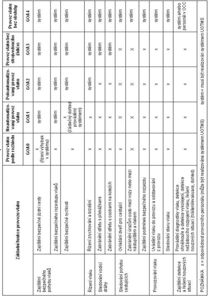
Tabulka 6 obsahuje požadavky na rozhraní systému, tj. rozděluje základní funkce systému podle dané stupně automatizace. Jestliže pražské metro definujeme jako systém režimu GOA2 dle [74], řídicí systém musí plnit základní funkce pro zajištění bezpečného pohybu vlaků, řízení vlaku. Další funkce mohou plnit jiné nezávislé subsystémy. Dle normy EN 62290 musí být systém UGTMS (tj. ASDŘ-D) schopen tvořit rozhraní se subsystémy uvedenými v předmětné normě, pokud jsou použity. Tabulka 6 popisuje rozhraní, prostředí a systémové hranice v souladu se zmiňovanou normou [74] a srovnává je s reálným stavem provozu Pražského metra; detaily jsou v práci [4].
| Legenda tabulky: Tučně vyznačené položky jsou v řízeném systému využívány a jsou součástí řídícího systému (ASDŘ-D). Kurzívou jsou označeny položky, na které má řídící systém návaznosti. | |
| ASDŘ-D (UGTMS) | Provozní řídící zařízení |
| Traťové zařízení (zahrnuje bodový přenos mezi kolejí a vlakem) | |
| Vlakové zařízení (zahrnuje lokalizaci, měření rychlosti a času) | |
| Systém datové komunikace (zahrnuje datovou komunikaci traťového zařízení, komunikaci mezi traťovým zařízením a vlakovým zařízením) | |
| Řízení | Ústřední rozhraní s personálem |
| Místní rozhraní s personálem | |
| Traťová zařízení (např. výhybky, návěstí a návěstidla, kolejové obvody, čítače náprav, traťová zařízení kontrolující rychlost, sousední řídící střediska, automatické zastavení, přejezdy) | |
| Stávající uzávorování | |
| Plánování provozu | |
| Informační systémy komunikace | Zvuková komunikace (např. komunikace s personálem, s cestujícími) |
| Stanice | Pomocná zařízení (např. výtahy/eskalátory) |
| Detekce ohně/ochrana proti ohni | |
| Detekce narušení nástupiště/tratě (např. cestující na kolejích) | |
| Rozhraní s jinými zařízeními (např. nouzové rukojeti, zařízení nouzového volání, zařízení pro detekce/uzavření nechráněného prostoru, odbavovací tlačítko/vlak připraven k odjezdu) | |
| Monitorování pomocí CCTV | |
| Informace pro cestující na trati | |
| Zvuková komunikace | |
| Vlak | Dveře, pohon, brzdy, zařízení propojující vlak (např. elektrické mezi vozidlové propojky) |
| Rozhraní s personálem obsluhy vlaku | |
| Zařízení pro detekci překážek, vykolejení, ohně/kouře | |
| Detekce nechráněného prostoru, zařízení pro uzavření nechráněného prostoru | |
| Rukojeť pro nouzové zastavení uvolnění dveří/nouzové tlačítko | |
| Rozhraní s jinými zařízeními (např. s osvětlením, vytápěním, větráním, klimatizací (HVAC), baterií) | |
| Diagnostika vlaku (pro údržbu) | |
| Stav vlaku (z hlediska způsobilosti k provozu) | |
| Monitorování pomocí CTTV | |
| Informace pro cestující ve vlaku | |
| Zvuková komunikace | |
| Infrastruktura | Kolej (např. detekce zlomené kolejnice) |
| Větrání tunelu (například detekce ohně a kouře) | |
| Systém detekce narušení | |
| Rozhraní s jinými zařízeními (např. tlakovými uzávěry) | |
| Trakční napájení | Řízení trakčního napájení |
| Vysokonapěťový vypínač | |
| Údržba | Systém údržby |
Funkce pro automatické vybírání jízdného s lokalizací a nástupištní dveře uvedené v tabulce nejsou v systému pražského metra zatím instalované, nicméně v případě dalšího rozvoje (například pro plánovanou trasu D, které cílí na GOA 4) je nutné uvedené funkce a bezpečnostní opatření dle EN 62267 [75] zvažovat.
4.4 Přenosový systém řídícího systému metra a UGTMS
Obecný popis systému metra vychází z popisu systému řízení pražského metra ASDŘ [4], a evropského standardu pro definici funkcí a parametrů řídicího systému pro řízení městské kolejové dopravy [74], tj. systém UGTMS. Z technického úhlu pohledu můžeme sytém metra rozdělit na systémy řídicí, řízené a ochranné či zabezpečovací, které mají vzájemné vazby a některé společné vstupy a výstupy, jak je uvedeno výše. Vstupem systému jsou informace z procesu plánování provozu, tj. plánované jízdní řády, rozpisy služeb a podobně. Výstupem systému je zajištění dopravního výkonu v požadované kvalitě a v režimu dopravním a snížení dopadů pohrom v případě režimu ochranném [4].
Tabulka 7 obsahuje obecný systém metra dle [4] a obsahuje přiřazení bloků a rozhraní systému (technických a funkčních) dle UGTMS, v návaznosti na obrázek 10, tabulku 6, a dle [63].
Tabulka 7 Obecný model systému metra.
| Oblast | Vstupy | Výstupy |
| Řídicí systém | vnější vlivy, plánování provozu, řízený systém METRO | zabezpečovací zařízení, řízený systém METRO |
| Zabezpečovací systém | vnější vlivy, řídicí systém | Řízený sytém |
| Řízený systém METRO | vnější vlivy, zabezpečovací systém, řídicí systém | řídicí systém, kvalita provozu a dopravní výkon, snížení dopadů pohrom (ochranná funkce metra) |
Uvedené funkce a členění dle UGTMS slouží pro vysokoúrovňové zadávací požadavky na systém. Neposkytují však detailní popis vazeb funkcí, parametrů jednotlivých subsystémů, nároků na bezpečnost a kvalitu. Zmíněné vlastnosti je nutné vždy specifikovat dle lokálních požadavků a podmínek návazných a nadřazených systémů, včetně vazeb na povrchovou dopravu, geologických a klimatických podmínek, míry ohrožení všech relevantních pohrom apod.
Dále se vymezíme především na požadavky a vlastnosti jádra systému UGTMS, které je kritickou částí systému řízení a jeho rozhraní, tj.:
- provozní řídící zařízení,
- traťové zařízení (zahrnuje bodový přenos mezi kolejí a vlakem),
- vlakové zařízení (zahrnuje lokalizaci, měření rychlosti a času),
- systém datové komunikace (zahrnuje datovou komunikaci traťového zařízení s provozním řídicím zařízením, komunikaci mezi traťovým zařízením a vlakovým zařízením).
Obrázek 12 popisuje vztah mezi teorií (odstavce 2.4.5 a 3.3), tj. obecným popisem systému a reálným stavem dle [10].
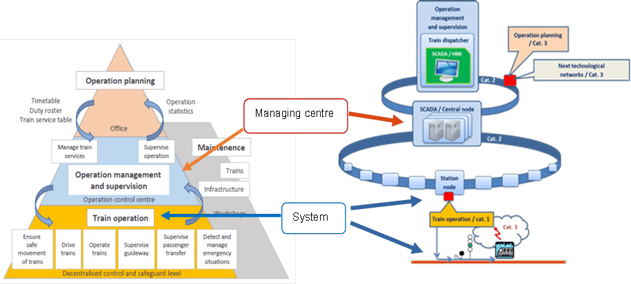
Na levé straně obrázku 12 je znázorněno členění systému UGTMS dle úrovně řízení (provozní plánování, řízení provozu, řízení vlaků), na pravé straně reálné uspořádání systému ASDŘ-D pro řízení dopravy pražského metra, tj. dispečerská pracoviště spojení komunikačním kanálem s centrálními uzly systému (na této vrstvě jsou znázorněné i rozhraní na další technologické či podnikové systémy), centrální uzly jsou propojené vlastní komunikační infrastrukturou se staničními, traťovými subsystémy. Červené body na pravé straně obrázku 11 značí kritická komunikační rozhraní a přenosové prostředí dle [63]. Označení Cat. 1-3 znamená kategorii přenosového prostření (systému) dle drážního standardu EN 50159 [76].
Při jisté míře abstrakce lze ke klasifikaci kyber-fyzického systému dle obrázku 8 z odstavce 2.4.5 přiřadit bloky systému UGTMS a reálné prvky řídicího systému ASDŘ-D pražského metra [63]:
- řídicí centrum (obrázek 8) – provozní řídicí zařízení – centrální uzly systému ASDŘ-D (respektive staniční řídicí uzly),
- systém (obrázek 8) – traťové a vlakové zařízení – staniční systémy a rozhraní, traťové přístupové body, vlakové komunikační jednotky, vlakové počítače,
- přenosové prostředí A, B (obrázek 8) – systémy datové komunikace – síť dispečerského centra, síť staničních a traťových uzlů, rádiové přenosové prostředí.
3.5 Výsledky analýzy znalostí a praxe z drážního prostředí a provozu metra
Předchozí práce v rámci magisterského a doktorského studia jsou zaměřené na:
- modelové případy (modelová stanice metra) [1,4,20,77,78],
- případové studie [10,63],
- analýzy příčin a následků železničních nehod [16,43,73,79,80],
- porovnání shody normativu a současné praxe v dopravě a průmyslu s legislativou a jejich kritické posouzení [21,40,78,81-83],
induktivní a deduktivní analýzy [43,48,84].
Na základě výše uvedených výsledků, a hlavně podle porovnání shody normativů a praxe lze konstatovat, že v praxi jsou zásadní nedostatky:
Uvedené práce analyzovaly mnoho nedostatků a kritických míst drážního systému, na která ve většině případech navrhují konkrétní procesní i technická opatření.
- Není řádně zavedeno vrcholové řízení s proaktivním přístupem a přístupem k integrálnímu riziku.
- Chybí mezioborová komunikace a vazba mezi jednotlivými vrstvami SMS.
- Požadavky na bezpečnost nejsou řešeny komplexně; nemusí být identifikována všechna prioritní (tzn. významná) rizika.
- Ve všech vrstvách řízení bezpečnosti chybí koncept All-Hazard-Approach.
- Absence konceptu Defence-In-Depth pro kritické objekty.
- Přístup k bezpečnosti a zabezpečení je v české i evropské legislativě pojat odděleně a neřeší vzájemné závislosti, které mohou ovlivnit bezpečnost.
- Drážní předpisy a normy dostatečně neřeší zabezpečení drážních zařízení.
- Neuvažují se vazby a toky za hranicemi systému.
Z hlediska systému řízení byly identifikované následující organizační zranitelnosti:
- Špatně provedená procesní analýza, špatně nastavené procesy a pracovní instrukce nerespektující moderní přístupy řízení bezpečnosti.
- Nedostatečná organizace, neflexibilní organizační struktura.
- Neznalosti požadavků z vyšších vrstev SMS nebo jejich nepochopení.
- Nedostatečná mezioborová komunikace, nejednotnost v terminologii.
- Nedostatečný monitoring, matoucí informace o zdrojích rizik systému směrem k vyšším vrstvám řízení a naopak.
- Nedostatečné vazby mezi procesy a rolemi v projektu, vzájemné závislosti jednotlivých rolí.
- Nedostatečnost kompetencí v dané roli, nejasná definice rolí a jejich odpovědnosti, nedostatečné vzdělání, školení a trénink.
Současná legislativa požaduje rozsáhlou množinu technických i organizačních opatření pro zmírnění známých slabin systému, zejména pokud se jedná o řízení provozu za normálních podmínek, případně při výskytu známých dopravních mimořádností, tzn. dle přístupu Defence-In-Depth (odstavec 2.1.7) jde o zabezpečený provoz při odchylkách nebo v abnormálních podmínkách. Jestliže okolní podmínky přesáhnou očekávanou a známou mez, například při kritických pohromách, legislativní požadavky, a tím i organizační schopnosti podniků začínají selhávat. Dalším aspektem vedoucím k selhání je také míra vynucování legislativy (tj. vynucování zajištění bezpečnosti).
Případové studie na systém řízení z pohledu kyber-fyzických systémů dále ukazují na následující fakta:
- Prvky aktivní a pasivní bezpečnosti jsou implementovány pouze na základě zkušeností, tj. nekoncepčně, bez stanovení stupnic kritičností aktiv a rizik, bez zohlednění propojení s důležitými okolními a nadřazenými systémy; z hlediska integrální bezpečnosti se jedná o jasné zranitelnosti v oblasti bezpečnosti systému.
- Není možné zajistit neomezenou dostupnost systému kvůli velkému počtu subjektů, které se na provozu podílejí za různých okolních podmínek; nicméně dostupnost systému lze zlepšit zvýšením informačního výkonu.
- Vzhledem k rozhraním systémů různých povah jsou včasnost a validita zpráv o poruchách směrem k uživatelům značně limitované (systémy mají různé požadavky na důvěrnost, dostupnost a integritu informací, jiné principy a opatření).
- Kontinuita provozu systému je ovlivněna dostupností systému, to znamená, že závisí také na informačním výkonu; každý subjekt zavádí do systému jisté nejistoty a neurčitosti, které degradují informační výkon, a proto je kontinuita systému ve skutečnosti závislá na subjektu s nejhorší mírou informačního výkonu.
- Přesnost systému je vždy méně či více omezena rozsahem, který zužován nízkým informačním výkonem, horším zajištěním informačních aktiv a vyšší systémovou komplexitou (složitostí).
Na základě analýzy příčin a následků železničních nehod byly analyzované následující problémy:
- Problémy na rozhraní člověk – stroj (HMI, angl. Human Machine Interface).
- Problémy na rozhraních systémů kyber-fyzických.
- Problémy na rozhraních systémů socio-technických.
- Stanovení odpovědností, a to ne jenom mezi subjekty, ale také mezi procesy systémů, tj. technologických děl.
Výše uvedené skutečnosti, zranitelnosti a problémy ukazují právě na složitost SoS, které jsou charakteristické svojí provázanosti, tj. interdependence. Interdependence dle znalostí uvedených v Kapitole 2 jsou dle jejich povahy fyzické, kybernetické, místní a logické [6] a za podmínek abnormálních a kritických (nadprojektových) vedou ke ztrátám systému, a způsobují, že systémy řádně neplní svoje funkce a ohrožují sebe a své okolí.
Zvláštní problémy, které vzájemně interagují, a je potřeba je na základě uvedených analýz v rámci SMS zvažovat, jsou:
- nehomogenity a anizotropie systémů a jejich prostředí – vedou k hysterezím,
- rozhraní systémů a procesů (HMI, kyber-fyzické, socio-technické, různé kritičnosti, aj.) – různé povahy rozhraní a jejich neurčitost stavů za jistých podmínek vedou k selháním,
- kaskádové jevy – vedou k eskalaci a vyšším dopadům selhání.